Made in Germany: developed and manufactured by Stucke Elektronik GmbH.
The GC (Generator & Grid Controller) variant brings protection, network monitoring and active grid-code control into a single device. It is the natural choice for connecting wind farms, solar plants, biogas units, hydropower stations and CHP installations to the medium- and high-voltage grid.
Positioning note: Compact+ GC is a Protection & Control IED for connecting a single generation unit to the grid (EZA/EZE, Grid Code). For Power Management with multiple generators in parallel operation, load sharing, automatic load shedding and diesel genset control, the classic SYMAP® BCG / ECG remains.
No generation plant in Germany, the UK or most of the EU can connect to the medium- or high-voltage grid without protection equipment that is type-certified to the local grid code. SYMAP® Compact+ GC carries FGH certificates for the German rules (VDE-AR-N 4110/4120) and implements the UK G99 functions; for other countries the configuration is adapted to the local grid codes.
Edition 2018-11
Medium Voltage
Generators connected to MV networks
FGH CERTIFIED
Edition 2018-11
High Voltage
Generators connected to HV networks
FGH CERTIFIED
UK ENA Engineering Recommendation
UK Grid Code
Generators > 16 A per phase
COMPLIANT
FGH (Forschungsgemeinschaft für Elektrische Anlagen und Stromwirtschaft e. V.) is the independent test house whose seal grid operators in Germany ask for. Without it, your DSO/TSO will not energise the connection.
Request your certification documents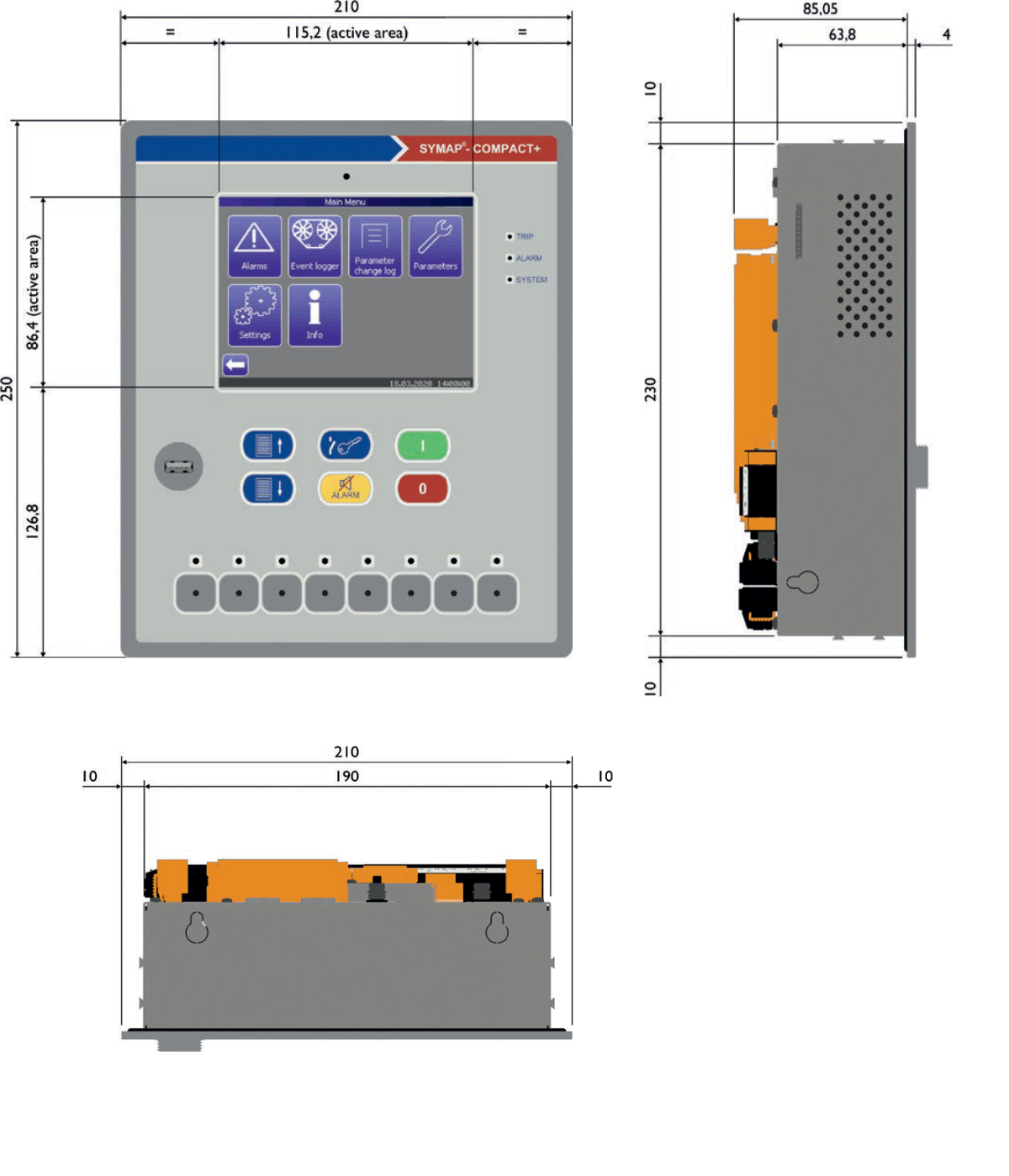 Click drawing to open at full size
| Housing (W×H×D) | 210 × 250 × 87 mm |
|---|---|
| Front plate (W×H×D) | 210 × 250 × 4 mm |
| Panel cut-out (W×H) | 192 × 232 mm |
| Mounting depth (behind front plate) | 85 mm |
| Active display area (W×H) | 115.2 × 86.4 mm |
| Mounting | Panel cut-out + integrated mounting clips |
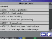
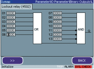
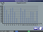
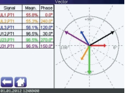
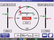
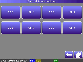
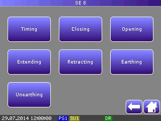
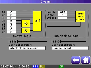
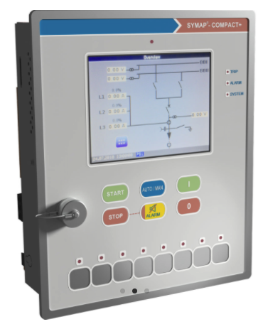
SYMAP® Compact+ has an HMI based on a color touch screen, with up to 4 configurable user pages. The engineer can directly monitor measurements, harmonics, vectors, synchronization and programmable logic functions on the device, without external tools.
IEC 61850 · KEMA Level A · GOOSE Performance Class P1
SYMAP® Compact+ uses GOOSE messages per IEC 61850-8-1 for real-time peer-to-peer communication between IEDs. With 128 virtual inputs and 128 virtual outputs, it enables extended use of GOOSE messages for interlocking, transfer trip, status signals and protection coordination. At the time of KEMA testing, Compact+ became the world's first IED certified for GOOSE Performance per IEC 61850-5 First Edition, with a KEMA Level A certificate (No. 74104125-OPE/INC 14-1082, April 2014).
GOOSE message path through two IEDs
Binary I/O (I/O time) is a separate, additional time and is not part of the shown communication + application time.
Application ≈ 0 ms follows the KEMA/UCA convention for event-driven architecture, where the processor (application) time is treated as 0 ms.
Ping-pong test: IED A sends an input message (GOOSE stimulus), IED B reacts and returns an output message (GOOSE response). The round-trip time is measured; divided by two it gives the communication (transfer) time. Compact+ is event-driven, so the application part reacts on the event itself and the response goes out immediately. The binary I/O part has its own time (I/O time).
SYMAP® Compact+ · KEMA measured
KEMA measured · P1Total reaction time: 1,84 do 3,05 ms (event-driven, application ≈ 0)
Communication time (GOOSE transfer), zoomed in
1,84 do 3,05 ms
Measured per the KEMA/UCA procedure (Performance Class P1). Even in the worst case the communication stays below ~3.1 ms.
Typical scan-based relay
illustrative exampleCommunication time:
Application (scan) time:
Total reaction time: 21 ms
Per KEMA/UCA test criteria for event-driven IED architecture, the processor (application) time is treated as 0 ms although in real devices there is always some internal processing time. The GOOSE test result for SYMAP® Compact+ represents the effective time of the tested signal path: event → GOOSE output → reception and reaction, without additional cyclic application wait.
The GOOSE Performance test requires reaction to the first received message without losses and without relying on later retransmissions, within defined time criteria that can range from P1 to P3 per IEC 61850-5. This is a mandatory pass criterion, which SYMAP® Compact+ met in all test scenarios.
Practical applications in substation environments
With 128 virtual inputs and 128 virtual outputs SYMAP® Compact+ opens a range of applications that previously required extensive cabling between cabinets, bays and protection devices. GOOSE messages per IEC 61850-8-1 carry this logic over Ethernet in real time.
Instant transfer of blocking signals between protection devices, without physical wiring, with transfer time in the millisecond range.
Remote tripping between protection devices over Ethernet, as an alternative to pilot cables in GIS and AIS feeders.
Reverse interlock schemes for busbar protection, without physical connections between bays in the substation.
Exchange of breaker positions, alarms and measurements between IEDs in the same or different substations.
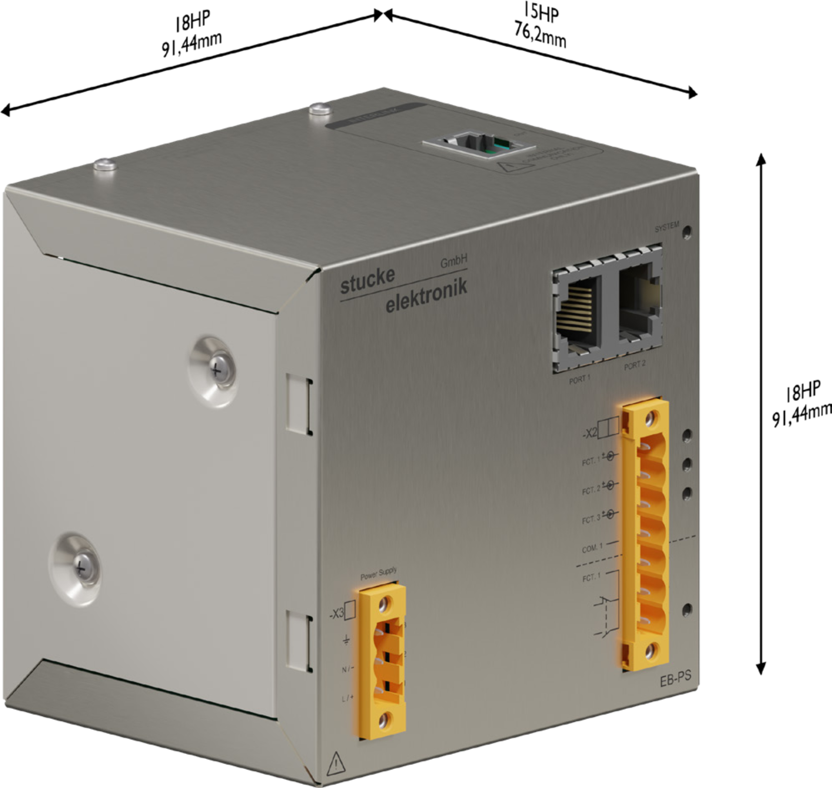
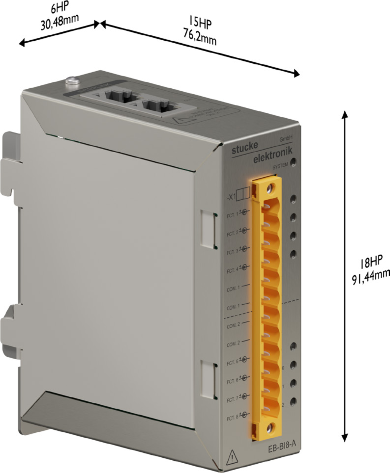
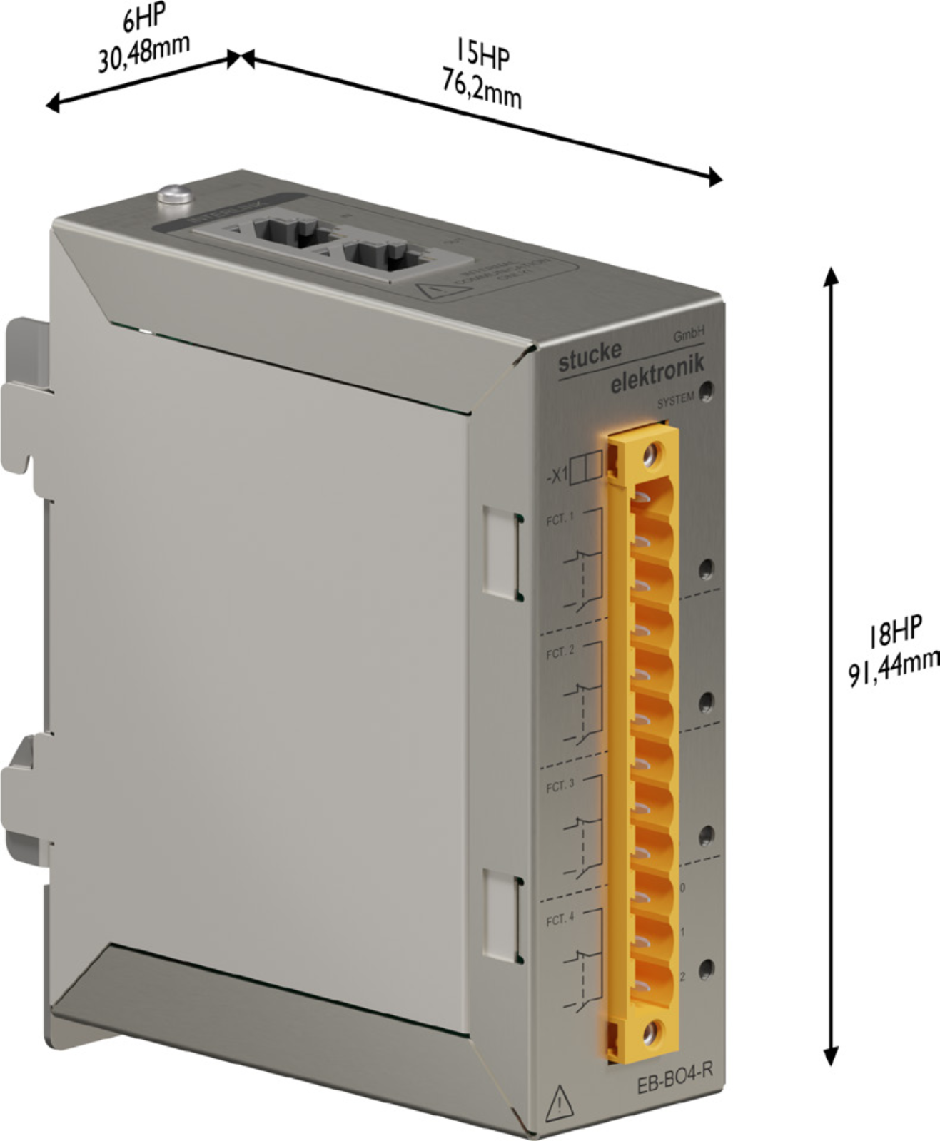

MODULAR EXPANSION
The number of binary inputs and outputs can be expanded using the system of extension boards. EBS consists of multiple board types with different functions, each designed for DIN TS35 rail mounting.
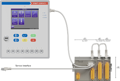
SYMAP® Compact+ connected to EBS extension boards via the Service Interface
Compact+ is a Protection & Control IED for a single bay, ideal for distribution and industrial switchgear, generation unit grid connection and switchgear retrofit.
Distribution and industrial substations. Feeder protection with directional and earth-fault detection, transformer protection, breaker control with integrated PLC and interlocking, IEC 61850 GOOSE communication.
Compact+ GC combines network protection (NA / Netz- und Anlagenschutz), generation unit controller (EZA / EZE) and Grid Code logic in a single device. Certified to VDE-AR-N 4110/4120 and G99 (FGH).
Utility-scale and commercial-scale solar plants, onshore wind, hybrid installations. Compact+ GC covers grid-code compliance, NA protection and QU control for a single connection point.
Run-of-river plants, small hydropower up to several MW. Generator protection, automatic grid synchronization, parallel operation and Grid Code compliance, all in one Compact+ unit per generator.
Biogas plants, natural-gas cogeneration, landfill and sewage gas. Compact+ GC provides parallel operation with the grid, network protection, synchronization and grid-code documentation for the DSO operator.
Motor bays (pumps, compressors, fans), feeder bays, transformer bays in process industry. Motor thermal model, start blocking, locked rotor, switchgear control, DCS/SCADA integration.
AC grid connection of BESS installations. Compact+ GC provides PCS transformer protection, synchronization, NA protection and grid-code logic. Interface to BMS and SCADA, SYMAP® is not a BMS replacement.
Modernization of legacy switchgear bays with a new Protection & Control IED in the existing footprint. Small front-door cut-out (192×232 mm), extended I/O through EBS modules, IEC 61850 integration with the existing SCADA system.
Single bays in stationary thermal, gas and diesel power plants. Compact+ covers feeder, motor and transformer bays, while a full multi-generator Power Management System remains on the classic SYMAP® BCG / ECG.
The choice starts from the application, not from the device type. Describe what you are protecting or controlling, and the combination of device type, variant, measurement inputs, I/O signals and communication options follows from the engineering analysis.
Start from the application; the configuration is then defined for the specific bay. SYMAP® Y/BC and SYMAP® Compact+ are not locked to a single use. The same application can be solved by different configurations, depending on CT/VT measurements, earth-fault measurement, CT1/CT2 allocation, the number of voltage systems, I/O signals, communication protocols, software-application options and control requirements.
| Application | Typical entry to configuration choice | Possible SYMAP® / Compact+ configurations | Critical note |
|---|---|---|---|
| Feeder | 3×I, Ig; Ug/3×U if required; breaker control; SCADA/IEC 61850; earthing regime of the network. | SYMAP® Y-F; SYMAP® BC; Compact+ +F1/+F2/+F3/+F4/+GC based on measurements, options and I/O. | Standard or optimal configuration? SYMAP® Y-F and Compact+ +F1/+F2/+F3 are standard configurations for most typical feeder bays. However, when the scheme requires multiple voltage systems, additional CT groups, DCVM monitoring, sync-check, more complex interlocks, communication or a larger number of signals, the optimal solution may be Compact+ +F4 or Compact+ GC. In such cases, a single device can consolidate functions that would otherwise be solved with several separate devices. |
| Overcurrent and earth-fault protection | 50/51, 50N/51N, 50G/51G, 67/67G; earthing method; CBCT/Ig; selectivity; auto-reclose if required. | SYMAP® Y-F; SYMAP® BC; SYMAP® Compact+ +F1/+F2/+F3/+F4/+GC, based on CT/VT and earth-fault inputs. | Selectivity is set according to network topology, earthing scheme and coordination with upstream and downstream protections. Compact+ additionally delivers advanced functions for the feeder: CLD (Cold Load Detection) for safe re-energising under load, CTS / PTS (Current / Potential Transformer Supervision) for measurement circuit monitoring, SOTF (Switch-On-To-Fault) for protection upon closing onto a fault, TIG / YG / VG (advanced earth-fault in isolated and compensated networks) and DP1 / DP2 Dynamic Parameters for adaptive protection per operating mode. |
| Motor protection | Thermal model, start/restart, locked rotor, unbalance, RTD/analog signals, contactor or breaker. | SYMAP® Y-M; SYMAP® BC; Compact+ +F1/+F2/+F3/+F4/+GC. | Do not omit BC. Compact+ choice depends on CT/VT, RTD/AI, DI/DO and control logic. For HIMAP MI retrofit, see the dedicated row. |
| Generator protection / generator-grid | Generator CT/VT, bus/grid VT, 25/25A, 32, 40, 27/59/81, grid code, EZA/EZE, AVR/governor signals. | SYMAP® Y-G; SYMAP® BC/BCG; Compact+ +F3/+F4/+GC based on the number of voltage systems and options. | +GC is natural for EZA/EZE and grid code, but is not the only generator-grid option. +F4 and SYMAP® Y/BC can be correct depending on the architecture. |
| Synchronization and parallel operation | Generator-bus/grid VT systems, close logic, 25/25A, speed/voltage regulator, PMS requirement. | SYMAP® Y-G; SYMAP® BC/BCG/ECG; Compact+ +F4/+GC for a single unit or connection point. | For a single unit Compact+ +F4/+GC may suffice. For multiple generators, load sharing, load shedding and bus-tie logic use SYMAP® BCG/ECG. |
| Multi-generator Power Management | Multiple gensets, bus-tie, PMS, load sharing, load shedding, blackout recovery, diesel genset control. | SYMAP® BCG/ECG as system PMS; SYMAP® BC depending on the project; Compact+ as a local bay or IED alongside the PMS. | For a central multi-generator PMS, SYMAP® BCG/ECG is used; Compact+ GC works as a local Protection & Control IED within the system. |
| Transformer protection | Primary and secondary side, CT1/CT2, 50/51, 50N/51N, 87T, REF, temperature/RTD. | SYMAP® Y-T/Y-TI/T2/T3; SYMAP® BC; Compact+ +F1/+F2/+F3/+F4/+GC with CT1/CT2 and 87 option where required. | CT1/CT2 economy: in specific applications a single IED measures and protects both the primary and secondary side, reducing the number of devices and simplifying field wiring. |
| Transformer differential / REF | 87T, REF, CT groups, vector group, stabilisation, earth fault, both transformer sides. | SYMAP® Y-TI/T2/T3; SYMAP® BC; Compact+ with 87 option and corresponding CT1/CT2 inputs. | Where the project requires redundancy, two independent relays are used; the single-IED solution is economical where redundancy is not required. |
| Line distance protection | 3×U + 3×I, zones, line parameters, auto-reclose, teleprotection/GOOSE, coordination. | SYMAP® Y-D; Compact+ +F3/+F4/+GC with ANSI 21 option and corresponding VT/CT. | For a new bay, SYMAP® Y-D or Compact+ is used. For existing HIMAP distance panels, a project-specific retrofit path is coordinated with HQ Hamburg. |
| Line / cable differential protection | 87L, CT at line ends, communication channel or fiber, time synchronization, line length. | SYMAP® Y-LD; Compact+ +F1/+F2/+F3/+F4/+GC with 87LD option and corresponding communication interface. | The choice is not limited to Y-LD; the Compact+ variant depends on CT/VT measurement and communication options. |
| Grid Code / EZA/EZE | VDE-AR-N 4110/4120, G99, NA protection, QU/Q(U), P/Q, 25/25A, SCADA/PPC communication. | Compact+ GC as a natural choice; Compact+ +F4 where the configuration fits; SYMAP® Y/BC depending on system architecture. | EZA/EZE grid-code regulator. PPC (Power Plant Controller) is the central system of the whole plant, a separate role. |
| DC systems and BESS | AC/DC monitoring, DCVM, DC earth fault, AC grid-side protection, BMS/PCS interface, SCADA. | SYMAP® Y-DC/Y-BAT; Compact+ +F3/+F4/+GC for AC/DC monitoring and AC connection. | SYMAP® is not a BMS nor a PCS. BMS manages the batteries; PCS the converter; SYMAP® the protection, measurement and communication layer. |
| Arc flash protection | Arc flash zones, light sensors, current criterion, quenching, trip logic. | SYMAP® ARC standalone or integrated with SYMAP®/Compact+ protection and trip logic. | SYMAP® ARC is a standalone arc protection system (light + current), not an ANSI function inside the SYMAP®/Compact+ relays. |
| Distribution networks | Selectivity, earthing regime, auto-reclose, feeder bays, SCADA/DMS, bay standardization. | SYMAP® Y-F/Y-D/Y-LD; SYMAP® BC; Compact+ +F1/+F2/+F3/+F4/+GC based on measurements and communication. | In distribution networks the priorities are selective coordination with upstream and downstream protections, the choice of earth-fault mode according to the neutral-point treatment (solid, resistive, compensated or isolated) and integration into SCADA/DMS via standardized protocols. Bay standardization simplifies engineering, spare parts and commissioning across many feeders. |
| Industrial systems and ATS | Grid, generator, transformer, motors, ATS, load priorities, interlocking, SCADA/DCS. | SYMAP® Y/BC; Compact+ +F3/+F4/+GC; SYMAP® ARC where required. | The choice depends on whether local bay protection or full system logic with multiple sources is required. |
| Marine / offshore / DP power | PMS, bus-tie, classification requirements, redundant networks, DP power, load shedding. | SYMAP® BC/BCG/ECG for system automation; Compact+ as local IED; SYMAP® ARC for arc protection. | DP here means Dynamic Positioning. Do not confuse with DP1/DP2 Dynamic Parameters in protection functions. For HIMAP retrofit on existing vessels, see the dedicated row. |
Note: the table is an orientation guide across applications, not a product limitation. SYMAP® and SYMAP® Compact+ are multifunctional platforms. The final choice is confirmed by engineering review based on the single-line diagram, CT/VT measurements, I/O signals, communication, software-application options, mechanical version and control logic.
Not sure which configuration suits your application?
Send the single-line diagram, the list of CT/VT measurements, I/O signals, communication requirements and a short description of the control logic. Our Belgrade engineering team can propose the suitable SYMAP® or SYMAP® Compact+ configuration, with verification of the Order Code and required options. Contact the engineering team
Provide your application data and we will handle the rest, typically within one working week:
CT/VT specifications, binary and analog I/O, protection functions, communication protocols (IEC 61850, Modbus, IEC 104).
We define the appropriate IED configuration matched precisely to your application.
The exact part number is generated according to your specifications and technical conditions.
A formal quotation is issued with delivery time and technical documentation.
Typical lead time, 5 WORKING DAYS from a complete inquiry.