
Made in Germany. All SYMAP® devices are developed, manufactured and tested at our headquarters in Hamburg, by the same engineering team that has been delivering protection systems since 1968.
SYMAP® is a digital protection relay for low-, medium- and high-voltage power systems. Thanks to its integrated protection functions and human-machine interface, it is an efficient and cost-effective solution for every type of switch bay, on ships, offshore platforms, in power plants, distribution substations, and renewable energy installations.
With three powerful microprocessors, SYMAP® provides comprehensive protection functions for generators, motors (synchronous and asynchronous), transformers, power lines and distributions. All protection functions can be activated simultaneously, with no limits on combining them.
SYMAP® can control up to five breakers per device, with all the necessary functions, display, control, interlocking, for optimal breaker management. A small integrated PLC allows individual interlocks from controlling functions, so commissioning engineers can implement plant-specific logic without any external controller.
For flexibility during commissioning and operation, both digital and analog outputs connect SYMAP® to the main switchboard. A wide range of serial interfaces and protocols supports communication with the central control system, whether substation SCADA, ship power management, or plant DCS.
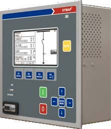
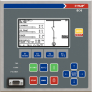
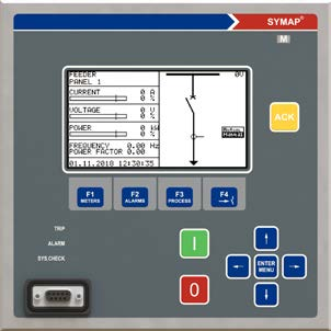
SYMAP® Y cost-effective version. Reduced front panel, large LCD, all core protection. Variants: EC (engine control), ECG (engine + generator + PMS), T1/T2/T3 (transformer), M (motor), G (generator + sync), F (feeder), LD (line differential), D (distance), DC (DC current/voltage), BAT (battery).
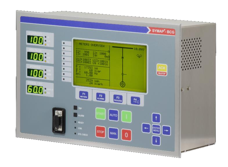
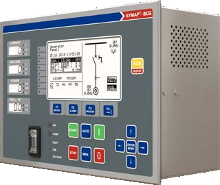
SYMAP® BC / BCG expanded version with 7-segment displays, 8 alarm LEDs, full LED indication panel, support for CMA extension board, complete Power Management System.
Instead of one separate central controller, each SYMAP® contains its own Power Management System (PMS) and ensures multiple redundancies. No matter which SYMAP® fails, the affected set drops out of automatic mode, but the other sets remain fully in PMS, and the entire power supply of a vessel or platform is independent of any other automatic system, internally redundant.
The PMS:
The PMS hardware and firmware is standardised and class-society certified identical across more than a thousand systems in service, so service technicians anywhere in the world know the same procedures.
SYMAP® addresses the relevant cyber-security aspects of a digital protection device with HMI capabilities. Type approval per IACS Unified Requirement E27 (Rev. 1) is held with major classification societies, as required for all new ship contracts under IACS rules from 1 July 2024.
SYMAP® devices have no remote access and contain only industrial information that does not require data protection. Engineering and service PC access is protected by passwords with operational timeout. The dedicated Cyber Security Manual documents the configuration measures required to maintain a cyber-secure setup, including physical protection of cabling and devices in restricted areas (engine room, locked cabinet).
In accordance with IEC 62443-3-3 Security Level 1 the international standard for industrial automation and control systems security.
IN THE FIELD
The SYMAP series is approved for switchgear installations, vessels, offshore platforms and renewable power plants.
Type approvals from every major classification society used by shipyards worldwide, plus standards for the European market, Korea, and IEC 61850 conformance.
Lloyd’s Register
American Bureau of Shipping
Det Norske Veritas
Bureau Veritas
China Classification Society
Polski Rejestr Statków
Nippon Kaiji Kyokai
Registro Italiano Navale
Korean Register
Conformité Européenne
V-Check (Korean Testing Certification)
IEC 61850 conformance certificate
Type approval certificates available on request, contact our sales team
SYMAP® provides more than 40 protection functions according to ANSI/IEEE C37.2 and IEC 60255 standards. All can be activated simultaneously there are no software-imposed limits on combinations. The exact set of functions depends on the device variant; see the variant matrix in the user manual or contact us for application-specific guidance.
| ANSI | Protection function | EC | ECG | T1 | T2 | T3 | M | G | F | LD | D | DC |
|---|---|---|---|---|---|---|---|---|---|---|---|---|
| 15 | Matching device (motorpoti) | ✓ | ✓ | |||||||||
| 21 | Distance protection | ✓ | ||||||||||
| 24 | Overexcitation protection | ✓ | ✓ | |||||||||
| 25/A | Automatic synchroniz., Synchro-Check | ✓4 | ✓4 | |||||||||
| 27 | Undervoltage, inst., def. time | ✓1 | ✓1 | ✓1 | ✓1 | ✓1 | ✓1 | ✓1 | ✓1 | ✓1 | ✓1 | |
| 27B | BUS undervoltage, def. time | ✓4 | ✓4 | ✓4 | ✓4 | ✓4 | ✓4 | ✓4 | ✓4 | |||
| 32 | Overload relay | ✓1 | ✓1 | ✓1 | ✓1 | ✓1 | ✓1 | ✓1 | ✓1 | ✓1 | ||
| 37 | Undercurrent protection | ✓ | ✓ | ✓ | ✓ | ✓ | ✓ | ✓ | ||||
| 40/Q | Loss of field, reac.power, impedance | ✓ | ||||||||||
| 46 | Reverse phase current | ✓ | ✓ | ✓ | ✓ | ✓ | ✓ | ✓ | ✓ | |||
| 47 | Phase sequence voltage | ✓4 | ✓4 | ✓4 | ✓4 | ✓4 | ✓4 | ✓4 | ✓4 | |||
| 49 | Thermal overload protection | ✓4 | ✓4 | ✓4 | ✓4 | ✓4 | ✓4 | ✓4 | ✓4 | |||
| 50BF | Breaker failure | ✓ | ✓ | ✓ | ✓ | ✓ | ✓ | ✓ | ✓ | ✓ | ✓ | |
| 50 | Overcurrent, instantaneous | ✓ | ✓ | ✓ | ✓ | ✓ | ✓ | ✓ | ✓ | |||
| 50G/N | Current earth fault, instantaneous | ✓ | ✓ | ✓ | ✓ | ✓ | ✓ | ✓ | ✓ | ✓ | ✓ | |
| 50/27 | Inadvertent energization | ✓ | ✓ | ✓ | ✓ | ✓ | ✓ | ✓ | ✓ | |||
| 51 | AC time overcurrent, def.time, IDMT | ✓ | ✓ | ✓ | ✓ | ✓ | ✓ | ✓ | ✓ | |||
| 51G/N | AC Ground overcurr., def.time, IDMT | ✓ | ✓ | ✓ | ✓ | ✓ | ✓ | ✓ | ✓ | ✓ | ||
| 51LR | Locked rotor | ✓ | ||||||||||
| 51V | Voltage restrained overcurrent | ✓ | ✓ | ✓ | ✓ | |||||||
| 59 | Overvoltage, inst., def. time, norm.inv. | ✓1 | ✓1 | ✓1 | ✓1 | ✓1 | ✓1 | ✓1 | ✓1 | ✓1 | ||
| 59B | BUS overvoltage, relay definite time | ✓4 | ✓4 | ✓4 | ✓4 | ✓4 | ✓4 | ✓4 | ✓4 | |||
| 64/59N | Residual overvoltage | ✓ | ✓ | ✓ | ✓ | ✓ | ✓ | ✓ | ✓ | ✓ | ✓ | ✓ |
| FF | Fuse failure (voltages) | ✓ | ✓ | ✓ | ✓ | ✓ | ✓ | ✓ | ✓ | |||
| 66 | Start inhibit | ✓ | ✓ | ✓ | ||||||||
| 67 | AC dir. overcurrent, def. time, IDMT | ✓4 | ✓4 | ✓4 | ✓4 | ✓4 | ✓4 | ✓4 | ✓4 | |||
| 67GS/GD | AC directional earth fault, definite time | ✓4 | ✓4 | ✓4 | ✓4 | ✓4 | ✓4 | ✓4 | ✓4 | ✓4 | ||
| 78 | Vector surge supervision | ✓ | ✓ | ✓ | ✓ | ✓ | ||||||
| 78S | Out of step tripping | ✓ | ✓ | ✓ | ||||||||
| 79 | Auto reclosing | ✓ | ✓ | ✓ | ✓ | ✓ | ||||||
| 81 | Frequency supervision | ✓ | ✓ | ✓ | ✓ | ✓ | ✓ | ✓ | ✓ | ✓ | ||
| 81B | BUS frequency supervision | ✓4 | ✓4 | ✓4 | ✓4 | ✓4 | ✓4 | ✓4 | ||||
| 86 | Electrical lock out | ✓ | ✓ | ✓ | ✓ | ✓ | ✓ | ✓ | ✓ | ✓ | ✓ | ✓ |
| 87G/M | Generator/Motor differential | ✓3,4 | ✓3,4 | ✓3,4 | ✓3,4 | |||||||
| 87LD | Line differential | ✓ | ||||||||||
| 87N | Restrict earth fault relay | ✓2 | ✓2 | ✓2 | ||||||||
| 87T | Transformer differential | ✓ | ✓ | |||||||||
| 94 | Trip circuit supervision | ✓ | ✓ | ✓ | ✓ | ✓ | ✓ | ✓ | ✓ | ✓ | ✓ | ✓ |
| 95i | Inrush blocking | ✓ | ✓ | ✓ | ✓ | ✓ | ||||||
| FL | Fault locator | ✓ | ✓ | ✓ | ✓ |
| ANSI | Protection function | BC | BCG |
|---|---|---|---|
| 15 | Matching device (motorpoti) | ✓ | |
| 21 | Distance protection | ||
| 24 | Overexcitation protection | ✓ | ✓ |
| 25/A | Automatic synchroniz., Synchro-Check | ✓4 | ✓4 |
| 27 | Undervoltage, inst., def. time | ✓1 | ✓1 |
| 27B | BUS undervoltage, def. time | ✓4 | ✓4 |
| 32 | Overload relay | ✓1 | ✓1 |
| 37 | Undercurrent protection | ✓ | ✓ |
| 40/Q | Loss of field, reac.power, impedance | ✓ | ✓ |
| 46 | Reverse phase current | ✓ | ✓ |
| 47 | Phase sequence voltage | ✓4 | ✓4 |
| 49 | Thermal overload protection | ✓4 | ✓4 |
| 50BF | Breaker failure | ✓ | ✓ |
| 50 | Overcurrent, instantaneous | ✓ | ✓ |
| 50G/N | Current earth fault, instantaneous | ✓ | ✓ |
| 50/27 | Inadvertent energization | ✓ | ✓ |
| 51 | AC time overcurrent, def.time, IDMT | ✓ | ✓ |
| 51G/N | AC Ground overcurr., def.time, IDMT | ✓ | ✓ |
| 51LR | Locked rotor | ✓ | ✓ |
| 51V | Voltage restrained overcurrent | ✓ | ✓ |
| 59 | Overvoltage, inst., def. time, norm.inv. | ✓1 | ✓1 |
| 59B | BUS overvoltage, relay definite time | ✓4 | ✓4 |
| 64/59N | Residual overvoltage | ✓ | ✓ |
| FF | Fuse failure (voltages) | ✓ | ✓ |
| 66 | Start inhibit | ✓ | ✓ |
| 67 | AC dir. overcurrent, def. time, IDMT | ✓4 | ✓4 |
| 67GS/GD | AC directional earth fault, definite time | ✓4 | ✓4 |
| 78 | Vector surge supervision | ✓ | ✓ |
| 78S | Out of step tripping | ✓ | ✓ |
| 79 | Auto reclosing | ✓ | ✓ |
| 81 | Frequency supervision | ✓ | ✓ |
| 81B | BUS frequency supervision | ✓4 | ✓4 |
| 86 | Electrical lock out | ✓ | ✓ |
| 87G/M | Generator/Motor differential | ||
| 87LD | Line differential | ||
| 87N | Restrict earth fault relay | ✓2 | ✓2 |
| 87T | Transformer differential | ✓ | ✓ |
| 94 | Trip circuit supervision | ✓ | ✓ |
| 95i | Inrush blocking | ✓ | ✓ |
| FL | Fault locator | ✓ | ✓ |
The SYMAP® hardware platform has multiple processors that monitor each other and handle different responsibilities. Because the firmware is modular and each function block runs on its dedicated processor, protection functions cannot be disturbed by control or controller activity and vice versa, a critical property for safety-relevant installations.
Measuring Unit
Protection functions; current and voltage measurement; pickup detection; tripping logic.
Control Unit
Control and controller functions; breaker operation; PLC interlocks; HMI interaction.
Recorder Unit
Event & protection function history; optional data recorder; permanent storage independent of supply.
Communication Unit
All communication protocols: Modbus RTU/TCP, IEC 61850, IEC 60870-5-103, PROFIBUS DP, GOOSE.
Each processor runs independently. Important protection functions are additionally laid out in double-redundant configuration with a second processor, so a single processor failure does not disable the relay.
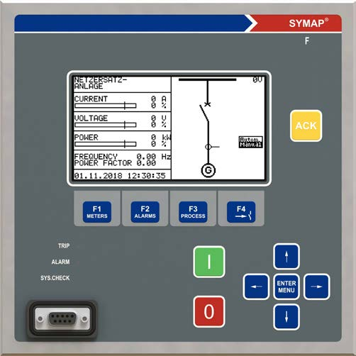
A large graphic LCD displays everything an operator needs to see at a glance: the position of every connected breaker, parameter settings, and event records. Graphics and measurements appear side by side on the same page no flipping between screens to correlate a value with its location on the mimic.
Programmed interlocks remain active even during manual control, so an operator cannot accidentally override a safety constraint.
The entire programming of the SYMAP® can be done with the keys on its front panel, no external programming device required. The programming is menu-tree driven, intuitive, similar to a modern handheld device. Optionally, parameters can be programmed via laptop, with the advantage of transferring parameter sets between SYMAP® units. Either way, on-site visits by manufacturer service engineers during commissioning are not required.
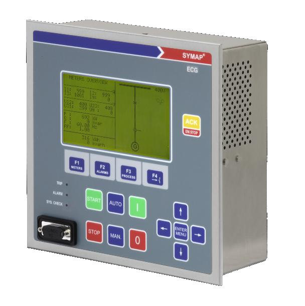
SYMAP® ECG, engine control + generator protection + PMS
SYMAP® can serve as the main bay controller for power management or substation systems, remote supervision, remote control, remote parameter setting, central event logging, central fault recording, plant power management.
Multiple protocols can run simultaneously on different physical interfaces, enabling, for example, IEC 61850 to a station bus while Modbus RTU continues to a legacy DCS, all from the same SYMAP®.
All connections to SYMAP® are made with terminal plugs on the back side of the device allowing the device to be exchanged easily, a critical property for retrofit projects and warranty replacements. If terminal plugs for the CTs are disconnected, the circuits are linked automatically so there is no disconnection in the CT circuit loops, safer for operators and instrumentation.
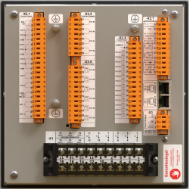
SYMAP® Y rear panel, pluggable terminal blocks (orange) for fast device exchange
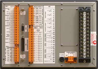
SYMAP® Y with optional CMA extension board interface (D-SUB 25-pole) and pickup inputs
* SYMAP® BC variants provide 6× feeder current, CT for measurement and CT for protection are wired separately (3 + 3).
Combined sensors are also supported (3× current + 3× voltage in one combined sensor).
A range of CMA extension boards adds I/O and special functions:
One extension board per device. Connection via 25-pole D-SUB cable supplied with the unit; CAN1 protocol with CAN2 redundancy.
| Dimensions (W × H × D) | SYMAP® Y: 192 × 192 × 103 mm SYMAP® BC: 279 × 192 × 146 mm |
| Weight | SYMAP® Y: 2.3 kg SYMAP® BC: 5 kg |
| Power supply | 12-36 V DC, 36-72 V DC, 80-300 V DC or 60-230 V AC |
| Power consumption | < 30 W |
| Service temperature | −20 °C to +70 °C |
| Storage / transport temp. | −40 °C to +70 °C |
| Humidity | < 80% |
| Degree of protection | Front panel IP54 / connections IP10 (per IEC 60529) |
SYMAP® comes in two device types (Y and BC), each with multiple sub-variants tailored for a specific application class. Each variant is a fully self-contained device, protection algorithms, hardware I/O, terminal block layout and HMI all match the application out of the box, so commissioning engineers don't have to build a generic relay into a specialised role.
EC, ECG, F, G, M, T, LD, DC, BAT
Relays with power management and diesel automation. Compact form factor (192 × 192 × 103 mm, 2.3 kg) with reduced front panel.
BC, BCG
Multifunctional protection relays with power management, diesel automation and differential protection. Larger housing (279 × 192 × 146 mm, 5 kg) with full front-panel indication.
Each variant is a fully self-contained device with protection algorithms and HMI tailored for a specific application class.
Engine control + generator protection + PMS
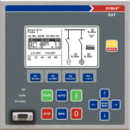
Battery applications, hybrid energy sources
Feeder protection, distribution / industrial substation
Motor protection, synchronous & asynchronous
All BC features include the standard SYMAP functionality plus:
BCG adds the integrated Power Management System, the flagship for marine and offshore main switchboards.
The full variant matrix, including which protection functions are standard, optional or unavailable per variant, is documented in the SYMAP® user manual. Send us your application and we will recommend the right variant.
ENGINEERED IN GERMANY SINCE 1968
“From a single feeder to a complete switchgear installation, one modular protection system.”
stuckeGROUP, Hamburg
Main switchboards on cargo, container, tanker, cruise, naval and offshore vessels, including drillships, FPSOs, AHTS, dive support and offshore wind installation vessels. Type-approved by leading class societies, IACS UR E27 cyber security ready.
Emergency power for hospitals, data centers, airports, industrial process plants. Fast load take-over, automatic synchronization with the grid, automatic load shedding under fault conditions.
Containerised generators, rental power, military deployable units, disaster-relief installations, rugged hardware, fast commissioning thanks to front-panel programming.
Run-of-river, small hydro, pumped storage. Generator protection (with differential), automatic synchronization, parallel operation with grid, island operation capability.
Distribution and industrial substations, feeder protection (with directional and earth-fault detection), busbar protection, transformer protection, breaker control with integrated PLC.
Onshore and offshore wind, utility-scale solar, hybrid systems. For grid-code compliant generation plants, see SYMAP® Compact+ GC.
Conventional thermal, gas-engine, diesel-engine and combined-cycle power plants, full protection coordination, communication to plant DCS over IEC 61850 or PROFIBUS DP.
SYMAP® ECG with the BAT application variant supports converter-controlled battery applications, for grid-scale BESS, frequency response, black-start and grid-forming.
Biogas plants, CHP units, landfill gas, sewage gas, gas-engine generator protection, parallel-with-grid and island operation, network & system protection.
Compact, retrofit-friendly variant with colour touchscreen and Grid Code certification (FGH / G99).
Compact+ details Configure order code1:1 plug-in retrofit for HIMAP, same connector layout, same panel cutout, modern algorithms.
SYMAP® R details Configure order codeModular arc-flash protection, tripping in under 2 ms with light + current cross-check.
ARC detailsSelection starts from the application, not from the device type. Describe what you protect or control, and the combination of device type, variant, measurement inputs, I/O signals and communication options will follow from engineering analysis.
Start from the application; the configuration is then defined for the specific bay. SYMAP® Y/BC and SYMAP® Compact+ are not locked to a single use. The same application can be solved by different configurations, depending on CT/VT measurements, earth-fault measurement, CT1/CT2 allocation, the number of voltage systems, I/O signals, communication protocols, software-application options and control requirements.
| Application | Typical entry to configuration choice | Possible SYMAP® / Compact+ configurations | Useful note |
|---|---|---|---|
| Feeder | 3×I, Ig; Ug/3×U if required; breaker control; SCADA/IEC 61850; earthing regime of the network. | SYMAP® Y-F; SYMAP® BC; Compact+ +F1/+F2/+F3/+F4/+GC based on measurements, options and I/O. | Standard or optimal configuration? SYMAP® Y-F and Compact+ +F1/+F2/+F3 are standard configurations for most typical feeder bays. However, when the scheme requires multiple voltage systems, additional CT groups, DCVM monitoring, sync-check, more complex interlocks, communication or a larger number of signals, the optimal solution may be Compact+ +F4 or Compact+ GC. In such cases, a single device can consolidate functions that would otherwise be solved with several separate devices. |
| Overcurrent and earth-fault protection | 50/51, 50N/51N, 50G/51G, 67/67G; earthing method; CBCT/Ig; selectivity; auto-reclose if required. | SYMAP® Y-F; SYMAP® BC; SYMAP® Compact+ +F1/+F2/+F3/+F4/+GC, based on CT/VT and earth-fault inputs. | Selectivity is set according to network topology, earthing scheme and coordination with upstream and downstream protections. Compact+ additionally delivers advanced functions for the feeder: CLD (Cold Load Detection) for safe re-energising under load, CTS / PTS (Current / Potential Transformer Supervision) for measurement circuit monitoring, SOTF (Switch-On-To-Fault) for protection upon closing onto a fault, TIG / YG / VG (advanced earth-fault in isolated and compensated networks) and DP1 / DP2 Dynamic Parameters for adaptive protection per operating mode. |
| Motor protection | Thermal model, start/restart, locked rotor, unbalance, RTD/analog signals, contactor or breaker. | SYMAP® Y-M; SYMAP® BC; Compact+ +F1/+F2/+F3/+F4/+GC. | Do not omit BC. Compact+ choice depends on CT/VT, RTD/AI, DI/DO and control logic. For HIMAP MI retrofit, see the dedicated row. |
| Generator protection / generator-grid | Generator CT/VT, bus/grid VT, 25/25A, 32, 40, 27/59/81, grid code, EZA/EZE, AVR/governor signals. | SYMAP® Y-G; SYMAP® BC/BCG; Compact+ +F3/+F4/+GC based on the number of voltage systems and options. | +GC is natural for EZA/EZE and grid code, but is not the only generator-grid option. +F4 and SYMAP® Y/BC can be correct depending on the architecture. |
| Synchronization and parallel operation | Generator-bus/grid VT systems, close logic, 25/25A, speed/voltage regulator, PMS requirement. | SYMAP® Y-G; SYMAP® BC/BCG/ECG; Compact+ +F4/+GC for a single unit or connection point. | For a single unit Compact+ +F4/+GC may suffice. For multiple generators, load sharing, load shedding and bus-tie logic use SYMAP® BCG/ECG. |
| Multi-generator Power Management | Multiple gensets, bus-tie, PMS, load sharing, load shedding, blackout recovery, diesel genset control. | SYMAP® BCG/ECG as system PMS; SYMAP® BC depending on the project; Compact+ as a local bay or IED alongside the PMS. | For a central multi-generator PMS, SYMAP® BCG/ECG is used; Compact+ GC works as a local Protection & Control IED within the system. |
| Transformer protection | Primary and secondary side, CT1/CT2, 50/51, 50N/51N, 87T, REF, temperature/RTD. | SYMAP® Y-T/Y-TI/T2/T3; SYMAP® BC; Compact+ +F1/+F2/+F3/+F4/+GC with CT1/CT2 and 87 option where required. | CT1/CT2 economy: in specific applications a single IED measures and protects both the primary and secondary side, reducing the number of devices and simplifying field wiring. |
| Transformer differential / REF | 87T, REF, CT groups, vector group, stabilisation, earth fault, both transformer sides. | SYMAP® Y-TI/T2/T3; SYMAP® BC; Compact+ with 87 option and corresponding CT1/CT2 inputs. | Where the project requires redundancy, two independent relays are used; the single-IED solution is economical where redundancy is not required. |
| Line distance protection | 3×U + 3×I, zones, line parameters, auto-reclose, teleprotection/GOOSE, coordination. | SYMAP® Y-D; Compact+ +F3/+F4/+GC with ANSI 21 option and corresponding VT/CT. | For a new bay, SYMAP® Y-D or Compact+ is used. For existing HIMAP distance panels, a project-specific retrofit path is coordinated with HQ Hamburg. |
| Line / cable differential protection | 87L, CT at line ends, communication channel or fiber, time synchronization, line length. | SYMAP® Y-LD; Compact+ +F1/+F2/+F3/+F4/+GC with 87LD option and corresponding communication interface. | The choice is not limited to Y-LD; the Compact+ variant depends on CT/VT measurement and communication options. |
| Grid Code / EZA/EZE | VDE-AR-N 4110/4120, G99, NA protection, QU/Q(U), P/Q, 25/25A, SCADA/PPC communication. | Compact+ GC as a natural choice; Compact+ +F4 where the configuration fits; SYMAP® Y/BC depending on system architecture. | EZA/EZE grid-code regulator. PPC (Power Plant Controller) is the central system of the whole plant, a separate role. |
| DC systems and BESS | AC/DC monitoring, DCVM, DC earth fault, AC grid-side protection, BMS/PCS interface, SCADA. | SYMAP® Y-DC/Y-BAT; Compact+ +F3/+F4/+GC for AC/DC monitoring and AC connection. | SYMAP® is not a BMS nor a PCS. BMS manages the batteries; PCS the converter; SYMAP® the protection, measurement and communication layer. |
| Arc flash protection | Arc flash zones, light sensors, current criterion, quenching, trip logic. | SYMAP® ARC standalone or integrated with SYMAP®/Compact+ protection and trip logic. | SYMAP® ARC is a standalone arc protection system (light + current), not an ANSI function inside the SYMAP®/Compact+ relays. |
| Distribution networks | Selectivity, earthing regime, auto-reclose, feeder bays, SCADA/DMS, bay standardization. | SYMAP® Y-F/Y-D/Y-LD; SYMAP® BC; Compact+ +F1/+F2/+F3/+F4/+GC based on measurements and communication. | In distribution networks the priorities are selective coordination with upstream and downstream protections, the choice of earth-fault mode according to the neutral-point treatment (solid, resistive, compensated or isolated) and integration into SCADA/DMS via standardized protocols. Bay standardization simplifies engineering, spare parts and commissioning across many feeders. |
| Industrial systems and ATS | Grid, generator, transformer, motors, ATS, load priorities, interlocking, SCADA/DCS. | SYMAP® Y/BC; Compact+ +F3/+F4/+GC; SYMAP® ARC where required. | The choice depends on whether local bay protection or full system logic with multiple sources is required. |
| Marine / offshore / DP power | PMS, bus-tie, classification requirements, redundant networks, DP power, load shedding. | SYMAP® BC/BCG/ECG for system automation; Compact+ as local IED; SYMAP® ARC for arc protection. | DP here means Dynamic Positioning. Do not confuse with DP1/DP2 Dynamic Parameters in protection functions. For HIMAP retrofit on existing vessels, see the dedicated row. |
Note: the table is an orientation guide across applications, not a product limitation. SYMAP® and SYMAP® Compact+ are multifunctional platforms. The final choice is confirmed by engineering review based on the single-line diagram, CT/VT measurements, I/O signals, communication, software-application options, mechanical version and control logic.
Not sure which configuration suits your application?
Send the single-line diagram, the list of CT/VT measurements, I/O signals, communication requirements and a short description of the control logic. Our Belgrade engineering team can propose the suitable SYMAP® or SYMAP® Compact+ configuration, with verification of the Order Code and required options. Contact the engineering team
Provide your application data and we will handle the rest, typically within one working week:
CT/VT specifications, binary and analog I/O, protection functions, communication protocols (IEC 61850, Modbus, IEC 104).
We define the appropriate IED configuration matched precisely to your application.
The exact part number is generated according to your specifications and technical conditions.
A formal quotation is issued with delivery time and technical documentation.
Typical lead time, 5 WORKING DAYS from a complete inquiry.